
This is going to be a long project! One team works six hours Tuesday and smaller team on Wednesday; a couple of experienced boat builders augmented with excited neophytes! Compare that with a crew of HMCo craftsmen working 10-12 hours days six days a week!
April 2016
We've decided it won't do for our ancient retirees to loft on the concrete floor, so we're lofting on a table. First step is to lay out a grid much like creating graph paper grids on the table; in this case the vertical lines will represent the distance between ribs. (Going from frame 0 at the bow on the right to the stern on the left. Horizontal grid lines are at 12' intervals up from the baseline.)
The table is divided into three segments:
-The upper half will be the half breadth lines, starting at the centerline and moving away from the centerline in 12' intervals as you go up the table.
- Bottom half will be the profile at the center line, with some notations such as sheer line which is at deck edge.
- An overlay section portraying the body plan, essentially the shape of the hull at each rib.
Thus the boat is sliced in three dimensions: rib by rib, in increments from the centerline, and in increments up from the baseline.
Note: the Table of Offsets measured dimensions at the exterior of the hull. The intent of lofting is to create molds which are offset measurements less the thickness of planking and thickness of ribs, since the ribs will be steam bent over the molds (to be precise, that dimension being measured perpendicular to the exterior plane at that point.)
At this point we should also note that HMCo probably didn't use this full lofting process. With the accuracy of NGH's half-hulls and Brown & Sharpe tool measuring, and the skill of craftsmen along with fairing of molds and on-scene adjustments in this high-production, profit-making environment, they'd have gone to making molds directly or perhaps from body plans. But in any case, we used the fundamentals such as taught nowadays with our volunteers and it proved to be an important visual for the team. It helped immensely to understand how ribs joined floor timbers and keel, how ribs would be faired to contour of hull, and angles for rabbets, back rabbets and bearding points.And as an exhibit, the table is very useful to explain the underlying traditional lofting and CAD processes. See discussion in Bray's Off Center Harbor video tour of HMM.
Picture One: Keith, Don and Bill have laid out the grid and are starting on the sheer line
October 2016
After summer break, our Roger Williams University Intern and short-term volunteer in between jobs continue the work
February 2018
Our high school Intern has been adding details and helping create an exhibit.
May 2019
Jim1 puts finishing touches on the exhibit. I say Jim 1 because it seems that volunteers come in limited number of names; hence Jim 1 and 2, Eric 1 and 2, Tim 1 and 2, Bill 1 and 2, and Keith 1 and 2. But there is only one Steve!
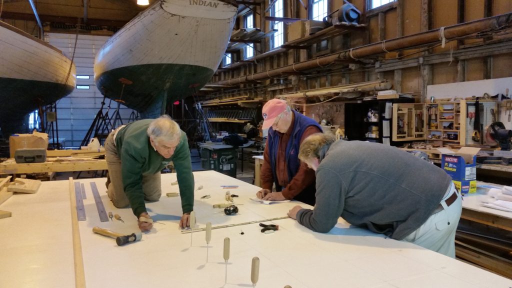
Image 1 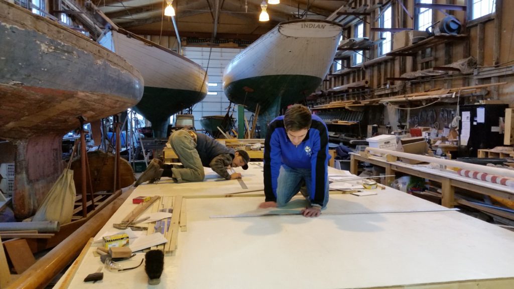
Image 2 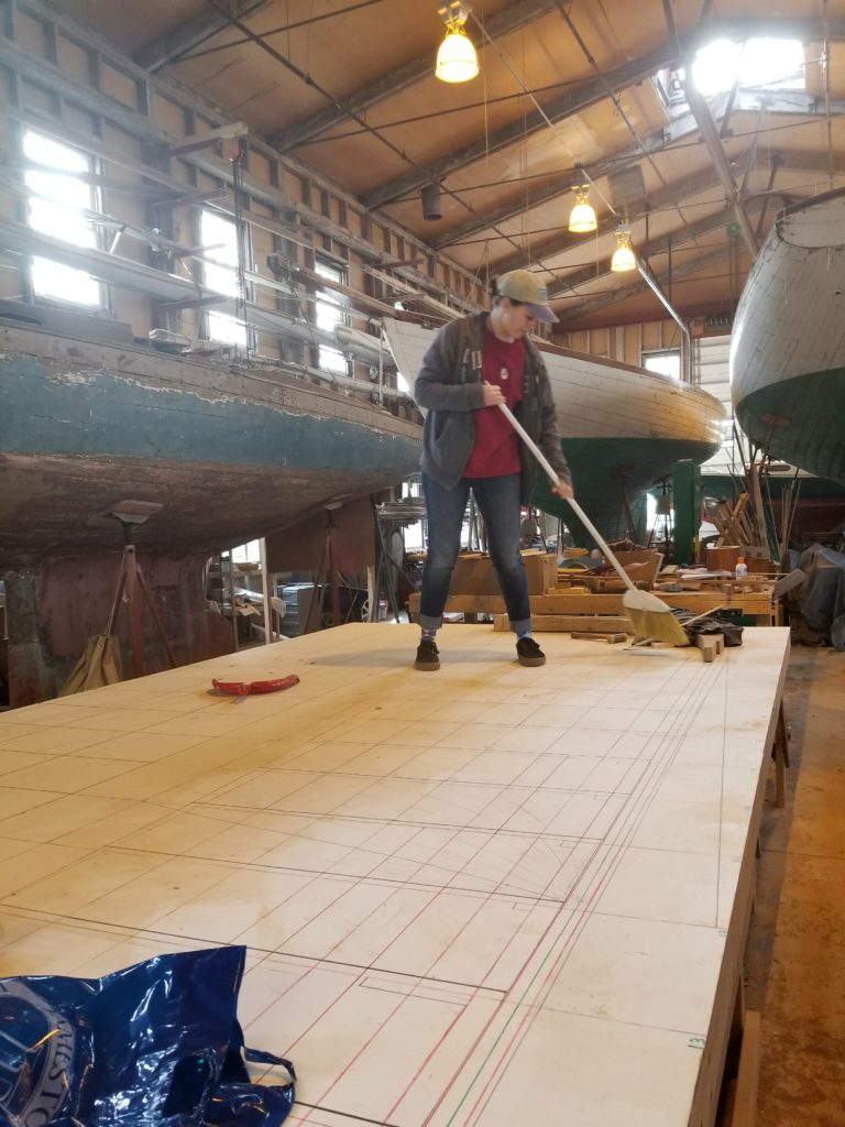
Image 3 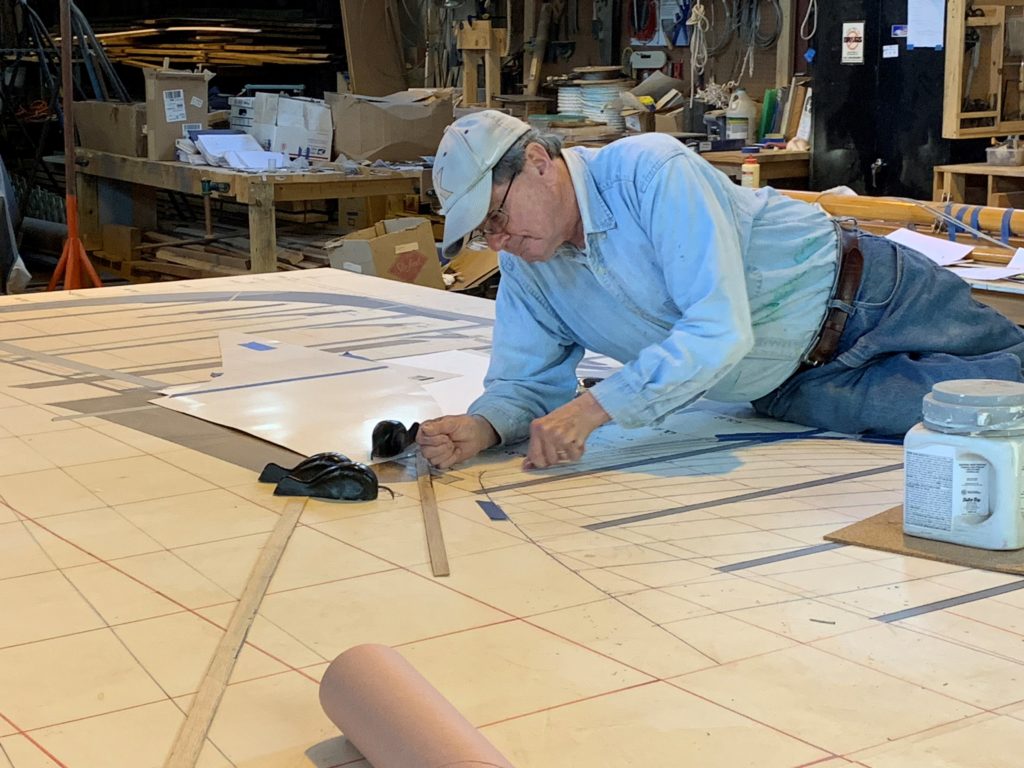
Image 4


