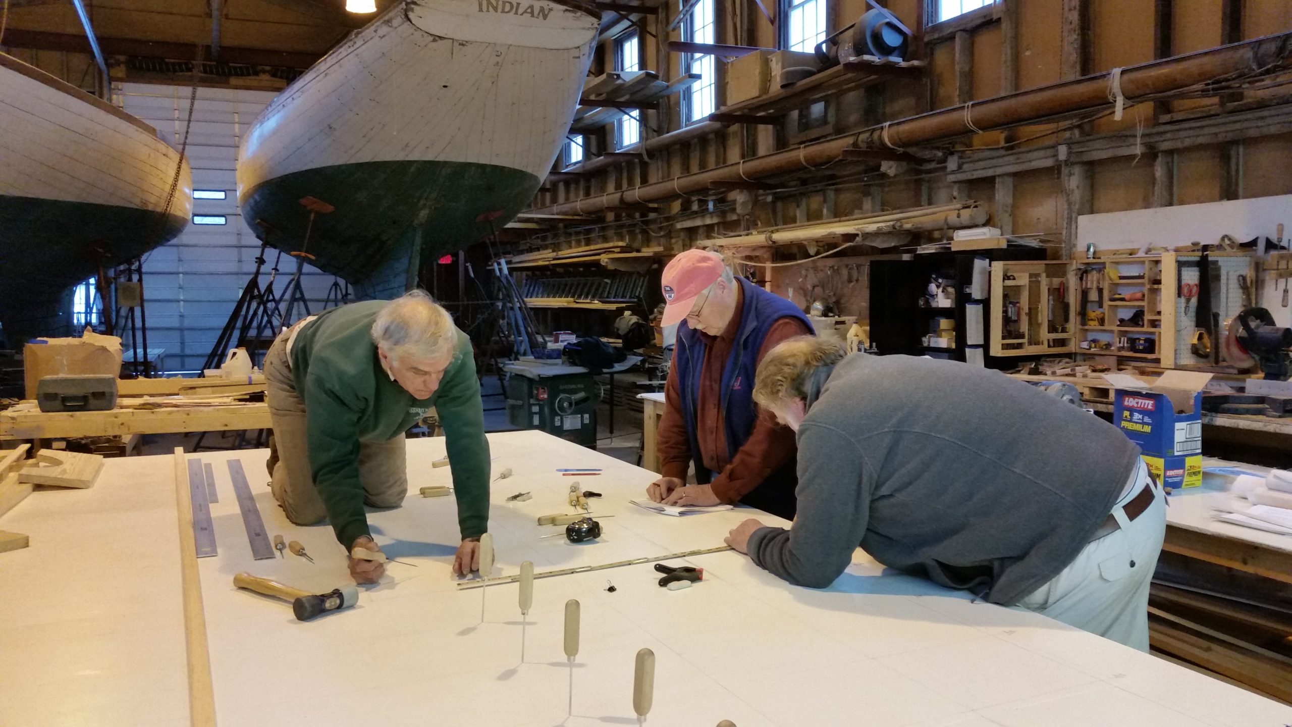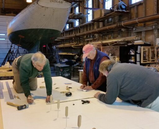
Before starting this segment, I forgot to mention that all these Table of Offset intersection points are ultimately placed on the lofting table, each contributing to creation of a line. In the case of picture 1 the sheer line. in picture 1 you can see picks have been placed at each of the points and when Bill, Keith and Don have completed all plot points they'll place a wooden batten against the picks to create a "fair" curve. To the extent that a pick is out of place it will be re-measured and checked against the offset book and corrections made as required. Typical sequence is to do the half-breadth and profiles first and then apply all corrections to make the Body Plan.
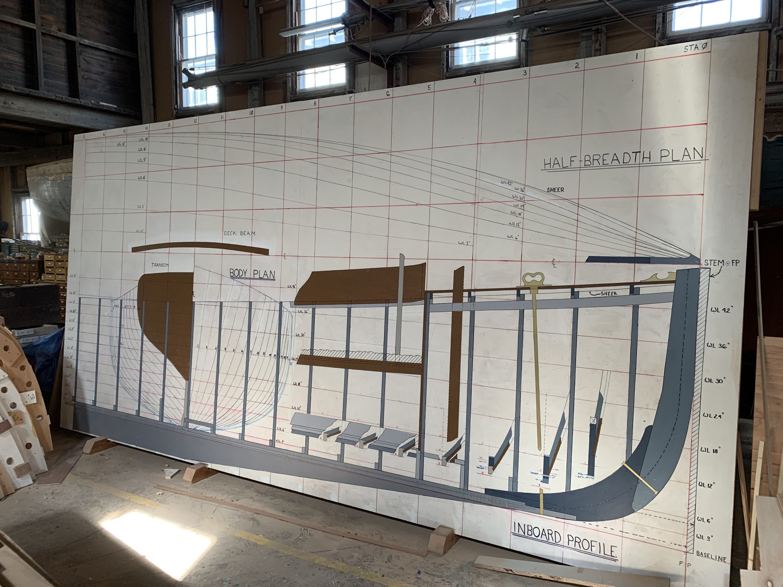
Picture 2 shows Jim1's creation with several embellishments from the draftsman's plan which helped our crew visualize the job at hand. Half- breadth at top and profile at bottom and body plan as insert at left.
Picture 3 is the forward part of the half-breadth plan showing the hollowness and flair of the bow. I'm sure Capt. Nat would have looked at this work and commented for some of the lines seem a little radical though you can see the effort to plot these accurately.
Picture 4 shows the fore end of the profile and there are many interesting notes here. The two stem pieces are drawn as an amalgamation of draftsman's drawing and offsets. The bearding line is clearly shown as well as the bolt holding both pieces together. The sheer at deck edge is shown, also the deck at centerline (from draftsman's drawing) from which camber will be determined. The thickness of stem piece is wider at top than bottom and is shown in the hatched area; this combines data from the half-breadth layout and will be used when shaping the stem.
The keel is actually two pieces; the keel and "false keel" and in cross section is a structural "T" shape. These are bolted together and into the floor timbers. The floor timbers are oriented perpendicular to the keel and they in turn are riveted to the ribs. Floor timbers lie aft of ribs in the forward half of the boat and forward of ribs in the after half! Confusing? The stem pieces, keel pieces, floor timbers and ribs, and transom with its knee at the stern (along with the sheer planks, discussed later) form the basic skeleton and are among the first pieces placed on the molds.
Creation of the rabbet where planks join keel and stem is "oak agony" for the angle of the planks meeting the keel and stem constantly changes as the bow and stern become narrower. In fact the "T' of the keel goes away at the fore end due to the acute angle of planking. So we added some insert pictures at frames 1-8 to show the angles and depths of rabbet in the keel. And the crew quickly learned about rabbets, back-rabbets and bearding lines and to cuss oak, dull chisels and planes!
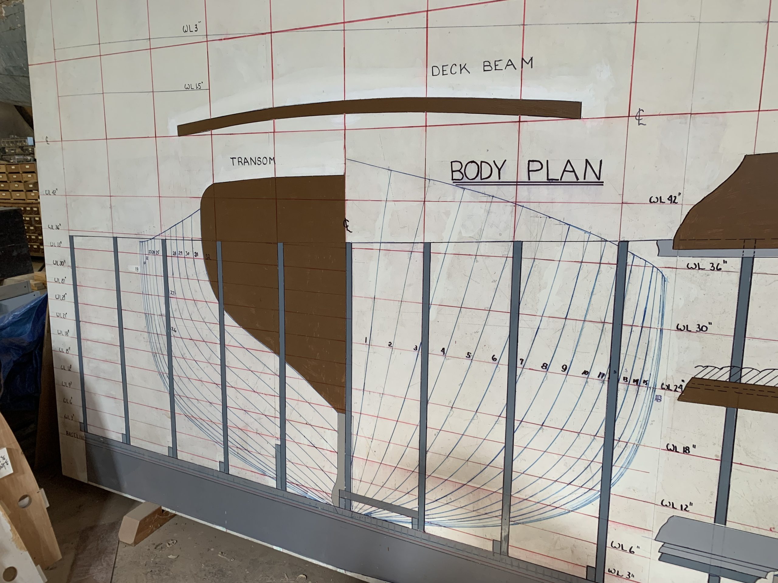
Picture 5 shows details of the body plan; on the right half all the ribs from midships to bow and on the left from midships to stern. Since the Transom is one of the skeletal pieces it is also depicted, colored brown. To aid in construction of deck timbers we created the longest one at top of the picture, also in brown. You'll note at the bottom of the transom there is a light gray strip with a bulb. This profile is created by plotting from Offsets the distance of the rabbet from centerline. The bulb therefore shows the size and location where the keel bulges out to accommodate piercing by the prop shaft. At the top of the picture is the profile of the longest deck beam, showing the camber. There are only few deck beams, about five at each end. most of the boat is open cockpit. As typical, camber doesn't change only the length of the deck beam, so this profile serves as a common pattern.

Image 1 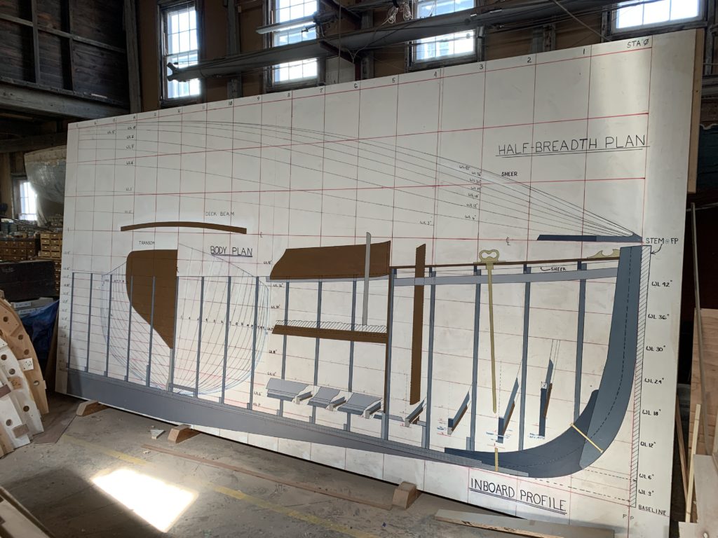
Image 2 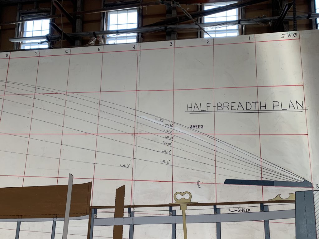
Image 3 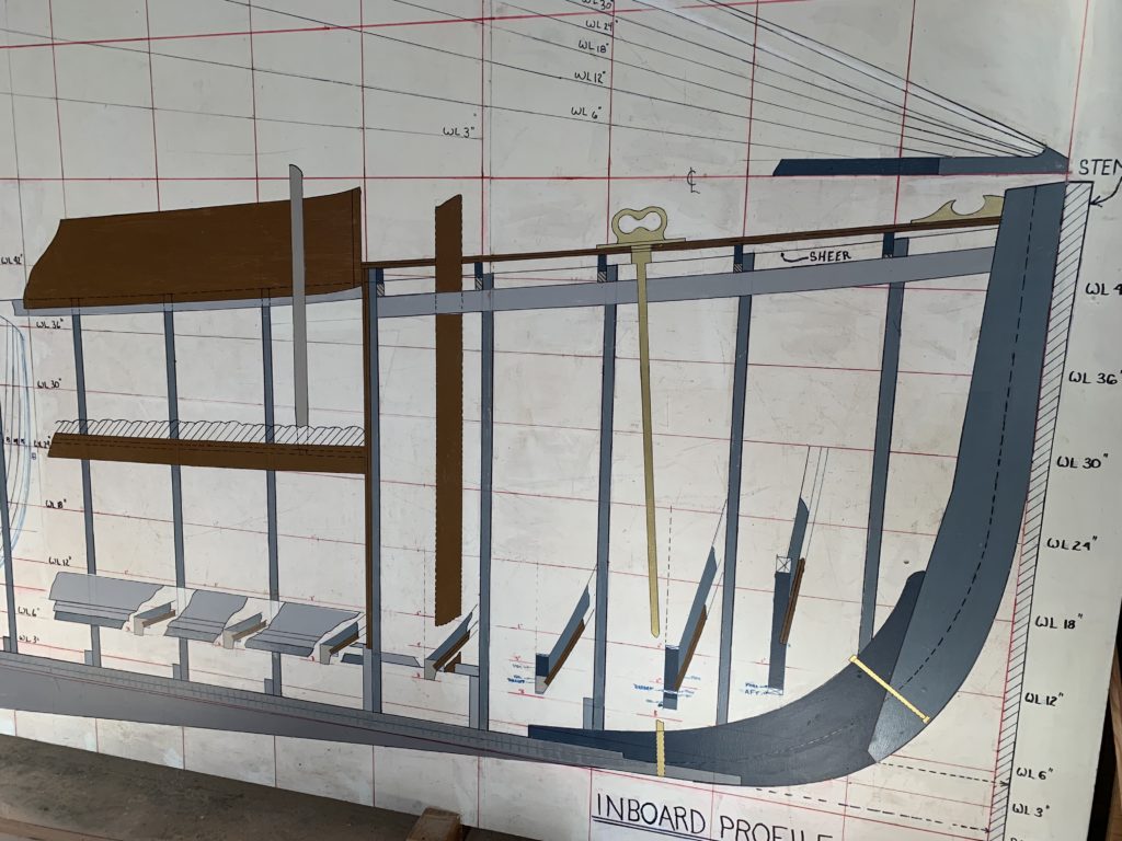
Image 4 
Image 5