March 23, 2022
Building an HMCo. Steam Engine: Part II
An apprenticeship focusing on metallurgy and fabrication at MIT brings an HMCo. steam engine to life
Guest Post by Dr. Daniel Braunstein
Click here to read Part I
The Plan
The stage had been set for our engine project in the fall of 2016, largely by happenstance, while leaning against an unassuming stack of drawers in building N52, within which contained thousands of plans from the Herreshoff Manufacturing Company. At the time Kurt Hasselbalch and I discussed the lab apprenticeship’s plan to fabricate an HMCo. steam engine for the planned Lighter, Stronger, Faster: The Herreshoff Legacy exhibition, the apprenticeship had already completed two full spring cycles. A model for planning this new HMCo. project emerged from our first project, the fabrication of the Lunenburg Foundry’s iconic Atlantic one-lunger engine. From the Atlantic project, I learned to expect that, in one semester, a student can either complete a single complicated cast part, two modest cast parts, or a single simple part plus two “average” machined parts. The first category, “a complicated part”, may require multiple cores with multi-part core-boxes or multi-part patterns, while the second category, a “modest cast part”, would have a straightforward core, such as a bearing shell. Not to disparage simplicity, but a “simple cast part” may not require a core. Students responsible for this latter category seem to find time to also fabricate a few machined components. Scope is important, and I was schooled as such by our earlier Atlantic project.
Such descriptions for “a part” belie the work required for completion. Each student-apprentice creates part CAD from museum supplied drawings, in which interpretation or technical archaeology is often required. At HMCo., and foundries in general, patterns were carved of wood by master patternmakers who would interpret engineering drawings in consultation with their foundry. Drawings for patterns themselves are therefore often not available. Hence, our students must hypothesize how parts were cast, along with their parting lines and arrangements of runners, gates, vents, and risers. Students would then generate CAD and CAM for the patterns and core-boxes. For many parts, pattern geometry is evident. For other parts, patterns may not be at all obvious. In our selected steam engine, the engine bed, with numerous undercuts and a side pull, falls in the former “complicated” category, as did the cylinder block. From their CAD and CAM, students fabricate patterns and core-boxes, mull sand, pack, and pour with help from our foundry friends. Once cool, parts are shaken out of their sand molds, cleaned, and machined to their final specifications. Usually, with other class obligations and scheduling conflicts, the pack-and-pour cycle requires a week, and our yield, while improving, has not quite crested 50%. Two full weeks, therefore, are generally required for a successful pour. Add a few more weeks for finish machining, assembly, and senioritis, and one finds themselves approaching spring semester’s conclusion in short order.
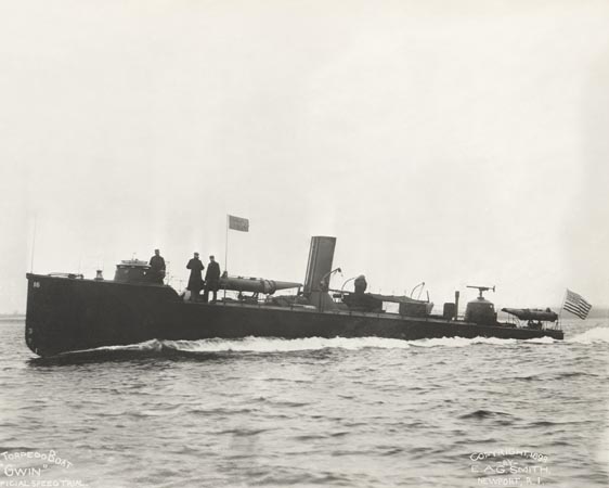
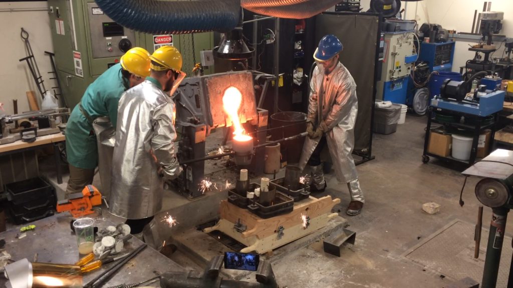
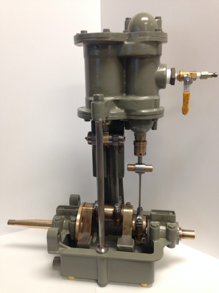
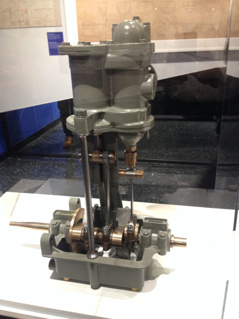
With six students and two spring semesters, we looked for an engine with approximately twenty parts, with each no heavier than what we were comfortable pouring – to the extent anyone is comfortable pouring 2500 °F molten iron! Complete drawings, too, were a plus. By the start of spring semester 2017, we had identified an HMCo. steam engine that satisfied these guidelines. We selected a 3-1/2” diameter bore x 3-1/2” stroke, single-cylinder steam engine with a spool valve. This engine was designed for use on the first Talbot class torpedo boats, TB-15 (USS TALBOT) and TB-16 (USS GWIN), commissioned in 1898. The engine circulated water in the tube boiler to prevent pockets of steam forming, which could cause overheating, damaging the boiler tubes. Because we did not have a steam system in which we would circulate condensate, and our facilities friends weren’t thrilled by the prospects of tapping an Institute steam line (nor was I, to be honest), students would run the engine without a load, using compressed air rather than steam. This was a perfectly reasonable and safe approach that did not compromise our educational mission, though there were a couple of colleagues from the Heat Transfer and Thermodynamics group who advocated for the real deal. “Nahhh,” I said. “Too risky.” We all understood.
A Puzzle
Sand casting is one of the most primitive practices, yet one of those processes that often leaves me dumbfounded. In principle, the process is simple. Sandcastle sand is shaped to form a cavity, molten metal is poured into the cavity, and, voila, a part is created. In truth, there is nothing “voila” about it. Sand casting is where thermodynamics, kinetics, material science, fluid mechanics, and heat transfer converge. It combines science, art, skill, and experience. In the lab, among the apprentices and teaching staff, we could tap into two of these areas on any given day. While this didn’t fully equip us to fabricate a Herreshoff steam engine, it apparently sufficed.
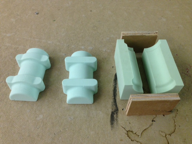
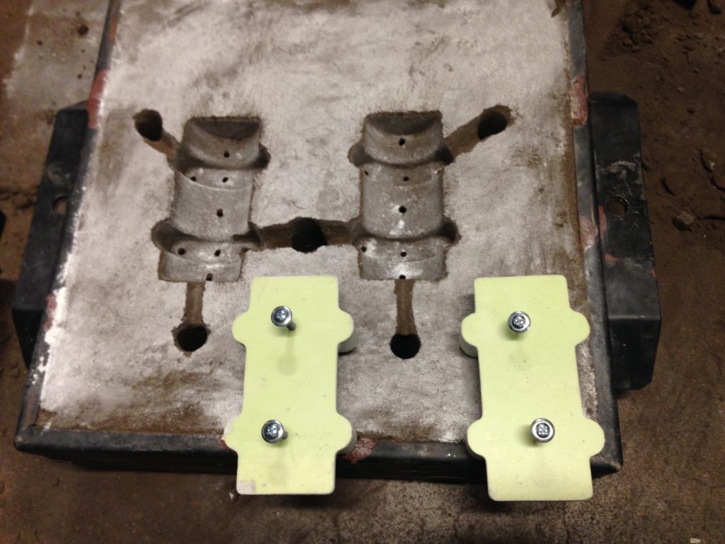
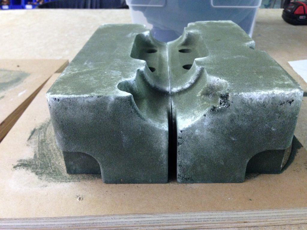
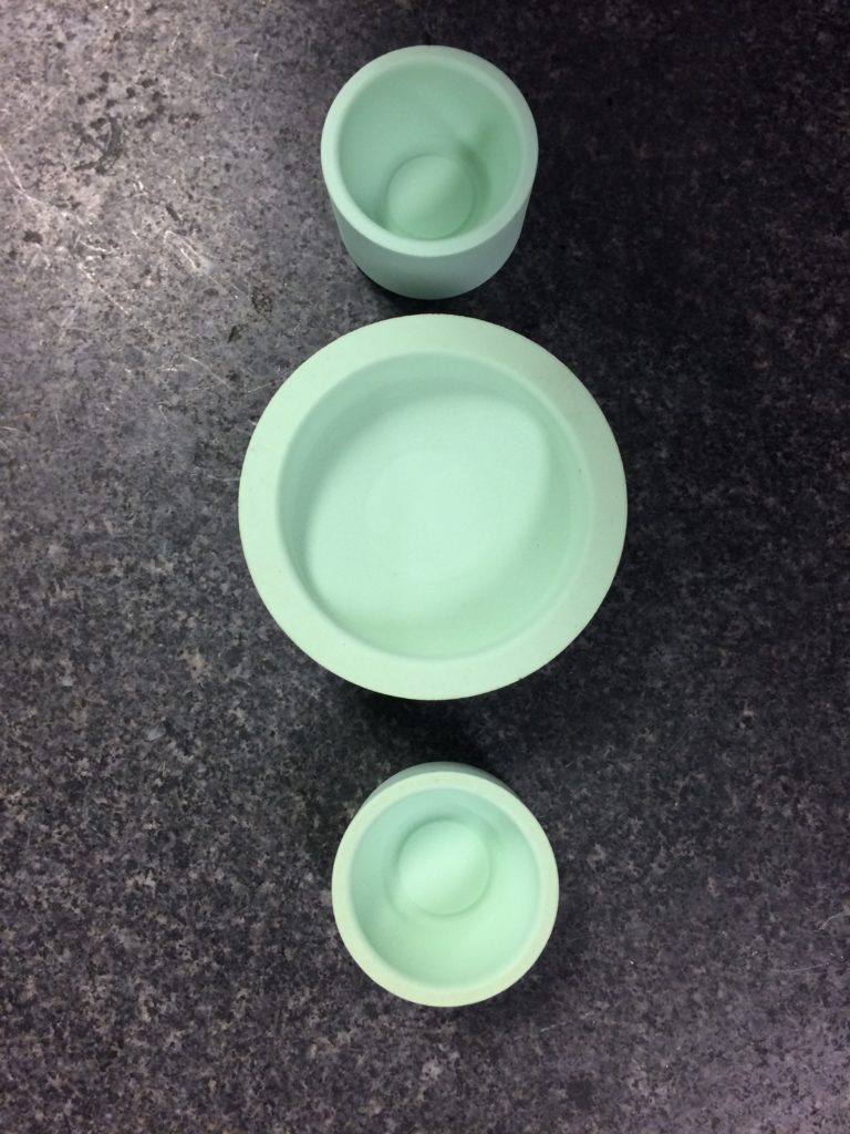
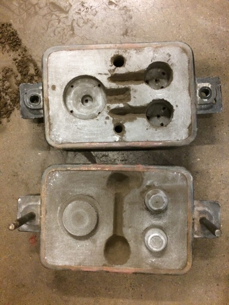
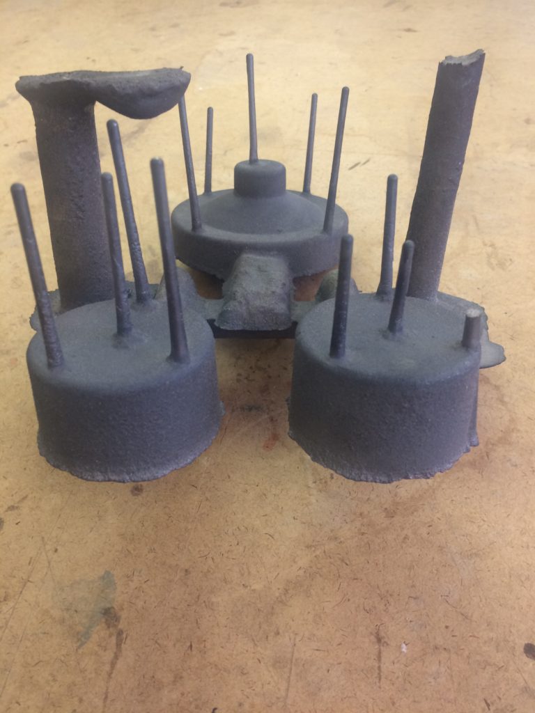
Ruminating on entropy aside, the geometrical considerations themselves are often head scratchers. To create a cast part, a pattern is first fabricated in the desired part shape. The pattern is largely a copy of the final part. Sand is packed around this pattern in such a way that the pattern itself can be removed from the sand, leaving a cavity into which metal is poured. In other words, a positive pattern is created to form a negative space in sand. If we wish to create a hole or hollow in the actual cast part, a new element called a core must be fabricated and assembled into the mold. This core is generally made of sand, using any variety of interesting binders, and is shaken out with the rest of the sand mold after casting. The core is consumed by the process. For example, casting a tube would require a cylindrical pattern to create the cylindrical depression in the sand and a smaller diameter cylinder core which would be placed into the mold. Metal would then only (hopefully!) fill the remaining tubular annular cavity. The core, therefore, is a positive part in the negative mold for the purposes of creating a negative space. But how does one make a core? The sand core is created by fabricating another mold called a core box. Once packed and cured, the core is removed from its mold and assembled into the main mold. The core box, may then be thought of as the negative space to create the positive part which creates the negative space in the final part. Reconciling this perpetual back-and-forth between negative and positive geometry is often more perplexing than a wrought iron bar puzzle.
Sand Empathy
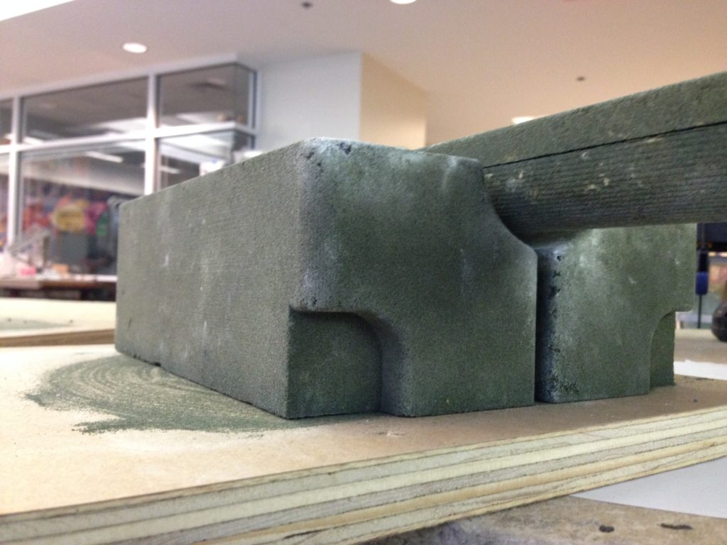
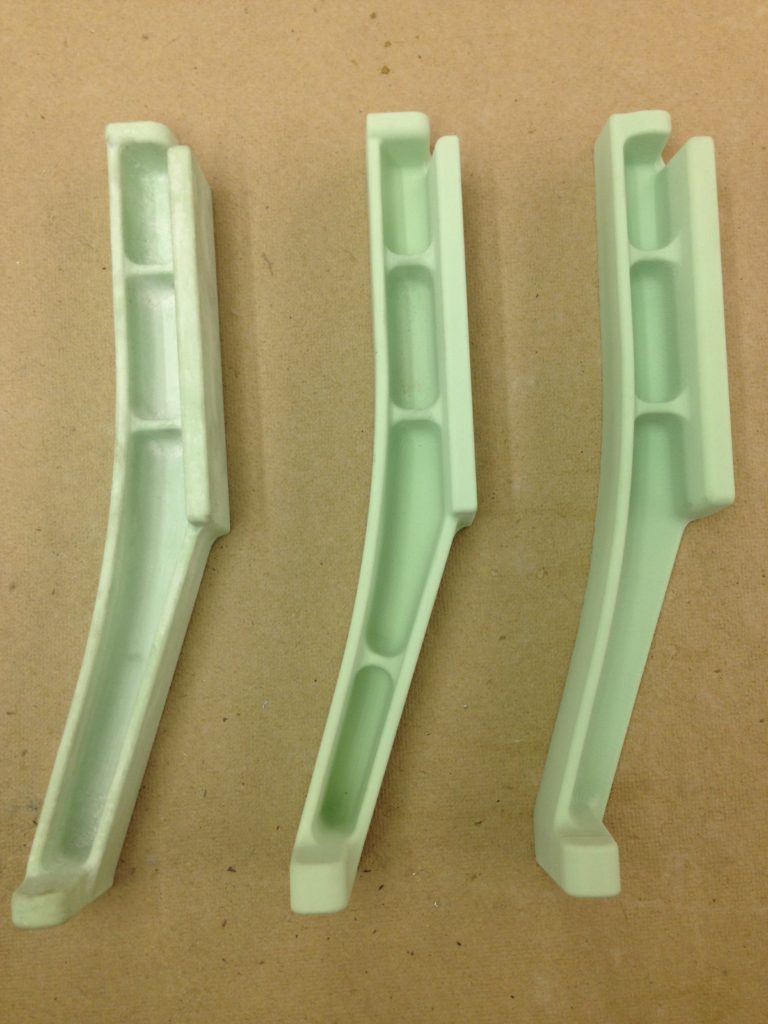
I ask the apprentices, “If you were sand in a mold, how would you like to be treated!?!” This leads to a concept I call “sand empathy,” and is meant to drive home the importance of adding draft to patterns and cores, as well as to think through possible benefits of multi-part patterns and coreboxes. It’s all about removing the patterns without destroying the molds.
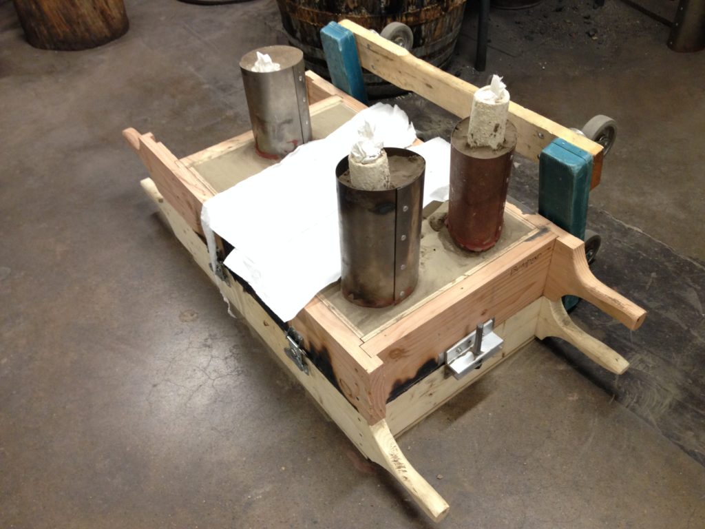
The pattern is rammed with sand from all sides, packed tightly in the mold, strong enough to withstand the forces of 2500 °F molten iron. Shear forces between pattern and sand are significant. Large vertical surfaces create enough shear to make pattern removal near impossible without tearing the sand apart. By introducing a slight angle to these sides, however, shear forces can be reduced significantly, and the pattern removed more easily as it separates from the sand. This slight angle is called draft. Draft angles vary based on the parts themselves, but we typically use angles of one to three degrees, depending on the application. The tedium of adding draft to each pattern surface is a necessary process, as will attest those who once thought they were saving time by just packing the flask with sand. “Be the sand,” I say. “Be the sand.”
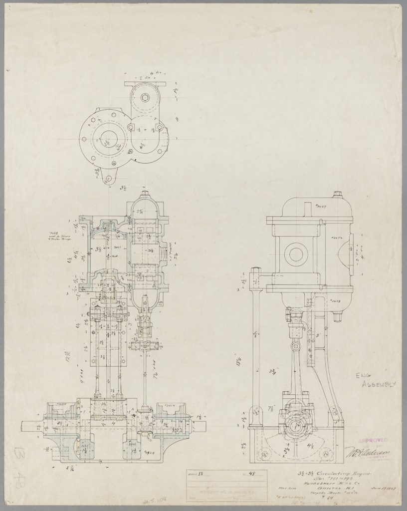
This circulating engine was designed for torpedo boat TB-15, the USS Talbot, commissioned in 1898. The engine circulated water in the tube boiler to prevent pockets of steam forming, which could cause overheating, damaging the tubes themselves. This engine was chosen because it was of appropriate size for a student project, had limited part count for our six seniors, and the drawings were complete and clear; plan courtesy the MIT Museum, Haffenreffer-Herreshoff Collection object ID# HH.5.01108
First Senior Class, Spring 2017
After reviewing the syllabus, grade policy, and schedule, the six students digressed from the material into a conversation about winter break. I presented a tube of drawings and my head cast a shadow against the powerpoint slide of VIGILANT (HMCo. #437) and VALKYRIE II. I shared the objective and import of this project while six seniors stood at the ready. I unrolled copies of prints of what was to be our next project. “I’ll take that one!” “What’s that?” “Can I do those?” they called. There was certainly no shortage of enthusiasm and I knew this group would dutifully advance this project and learn a great deal along the way.
Work that first week was divvied up according to the loose categories I described earlier. This necessarily meant that not all parts were going to be completed by end of term. I admired that this group knew they were contributing to, not completing, a project. Their work would represent at most half the components, but would most certainly advance our understanding and experience, which would allow next year’s group to complete the engine.
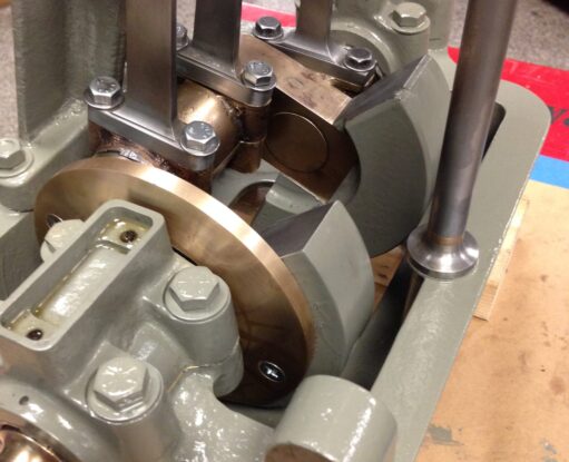
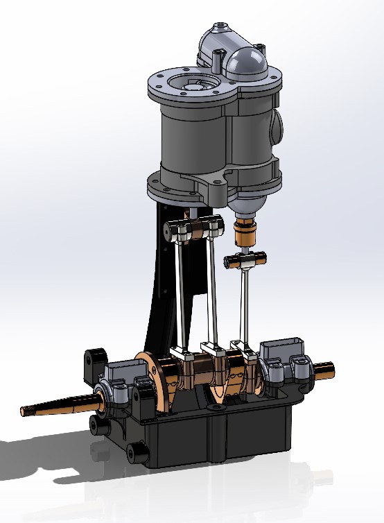
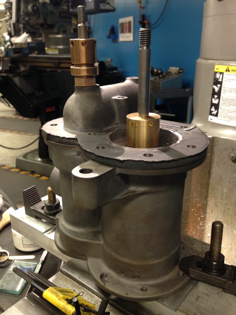
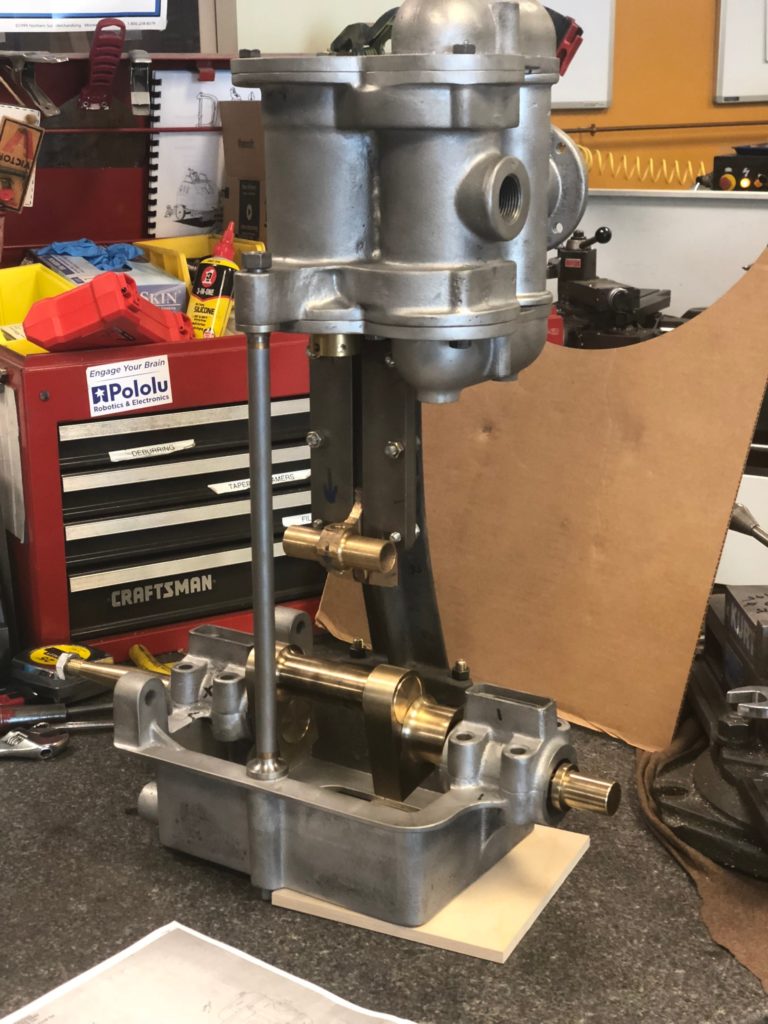
The Heart of the Engine
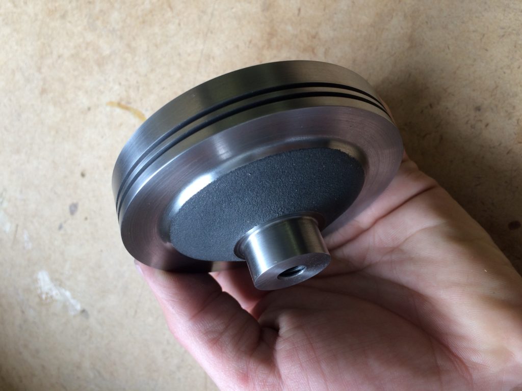
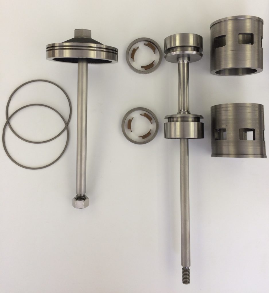
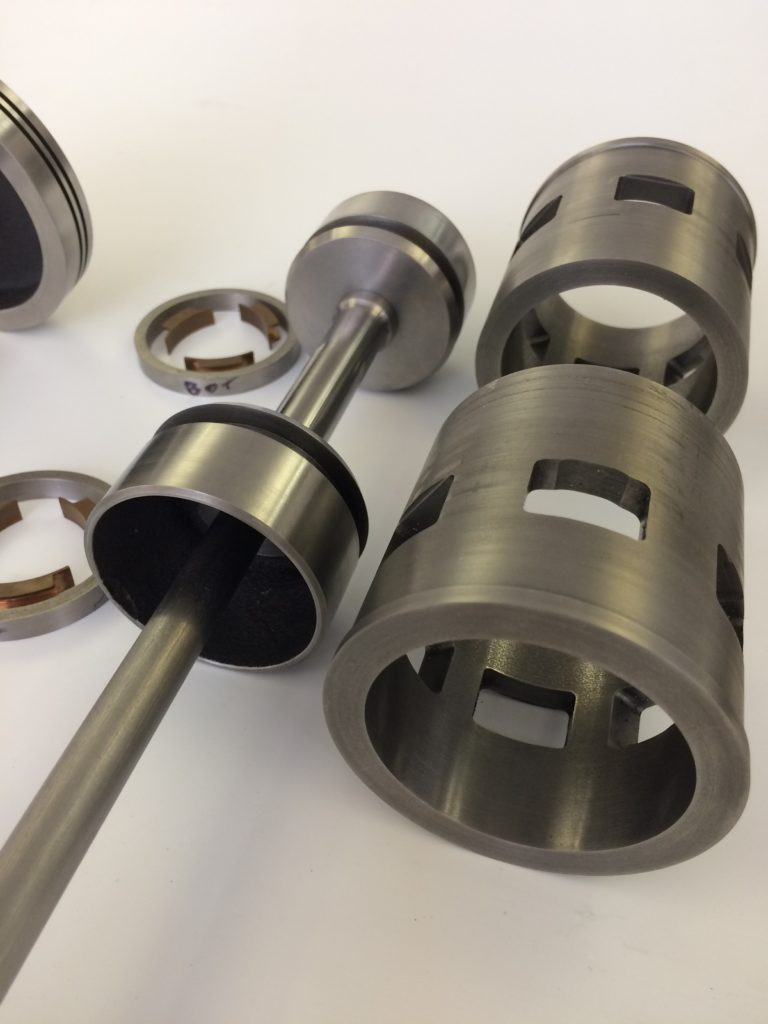
Architecturally, the engine may be thought of as having two primary areas, and each area with its own anchor parts. One, the bottom end, comprises the crankshaft, main bearing caps, and base. The base and crankshaft are the bottom end’s primary parts. The other area, the top end, is anchored by two cylinder caps (Shirley’s troublesome parts – see Part One of this story), and the cylinder, which I consider the Heart of the Engine. All these elements are held together by connective tissue – connecting rods, bearings, cross slides, piston, valve, rings, etc.
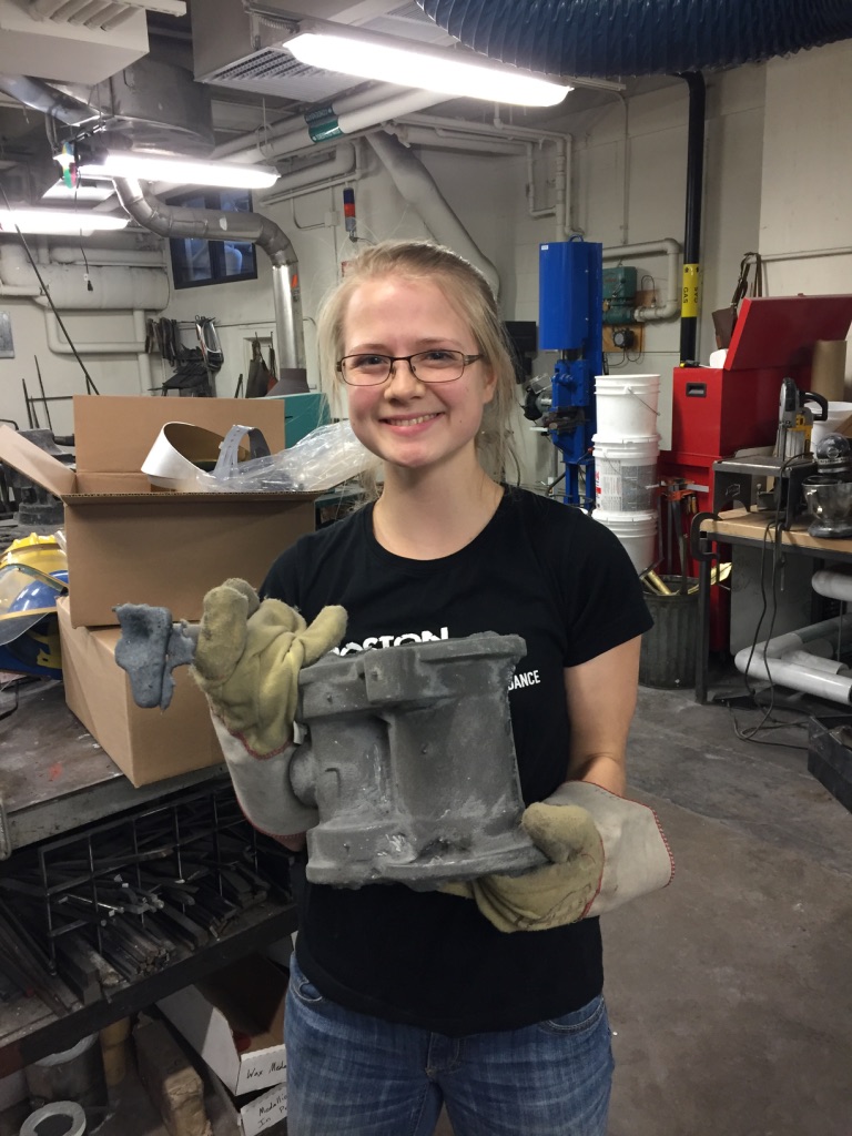
Colleen owned the cylinder block. I had no concerns about Colleen taking this challenge. Determined, earnest and effective, Colleen would get it done. Colleen was the middle of three MIT sisters, all ROTC, all highly effective, thorough, prepared, and thoughtful. Colleen was a sought-after mentor to her peers and an awesome person to have in the lab.
The cylinder was the heaviest and most complicated part to be completed by a student apprentice. It required two cores for the main piston and spool valve, two cores to connect the intake and exhaust passages in the upper and lower cylinder, and a core for the intake. Each core-box was constructed in multiple pieces to reduce shear forces on the cores themselves, and the cores were glued together, using a high temperature core-paste which has been dubbed “Sriracha sauce” by the students. (Note to foundries: If you ever encounter a young engineer referring to core paste in this manner, know they probably came through our program. It is now standard parlance.)
To be expected, Herreshoff drew the cylinder with thin-walled uniform sections, which meant deep sweeps and heavy cores. Finish machining involved a fairly easy facing operation to flatten the cylinder’s top and bottom, and a fairly nerve-racking boring operation of the cylinders themselves. We are optimists, but are keenly aware that each subsequent operation is an opportunity to introduce an error. With the help of our foundry partner down the hall, Mike Tarkanian, Colleen successfully cast her cylinder in the first attempt – remarkable. Truly remarkable, really. Colleen worked with our project technician Bill Cormier to machine the cylinder, while our long-time friend at MIT Central Machine, Scott Spence, repaired a little thing or two with brazing rod.
This cylinder became the rallying part for the project. The Heart of the Engine was complete and waiting for others to breathe life into it.
The Heads
The peskiest parts, the cylinder heads, required the work of three students over the course of both spring semesters. This first cycle, Larkin and Priscilla chipped away at two different approaches for these parts. These parts each contained two cores, which were not in and of themselves daunting. But the parts were complicated by a non-planar parting line, and most troubling, pushed the limits of thin walled sections. Both students attempted at least two pours in varying degrees of success. They tried different arrangements for risers and gating, following advice from U.S. Navy Foundry Manual and the standard Gating and Risering book from the American Foundrymen's Society Cast Metals Institute. In short, for us, these parts were not a walk in the park.
We did not close the 2017 term with complete cylinder heads, but we advanced our understanding of the issues, and developed an appreciation for the limits Nathanael Herreshoff pushed. These cylinder heads were thin walled sections that would cool before we could fill them. Success required careful attention to gating, venting, and pour temperature. We needed another term.
In addition to the engine project, our student-apprentices acted as lab assistants to students enrolled in one of the department’s design-build classes. It is during this class that the staff and senior apprentices identified a particularly talented fabricator with a perfect attitude and disposition for the apprenticeship. We took an active interest in her work and encouraged her to apply for next year. Shirley was to become our Colleen, and, building on Larkin and Priscilla’s work, would be the one to bring both cylinder heads over the line.
The Base and the End of Term
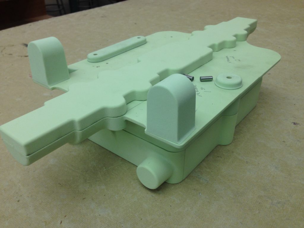
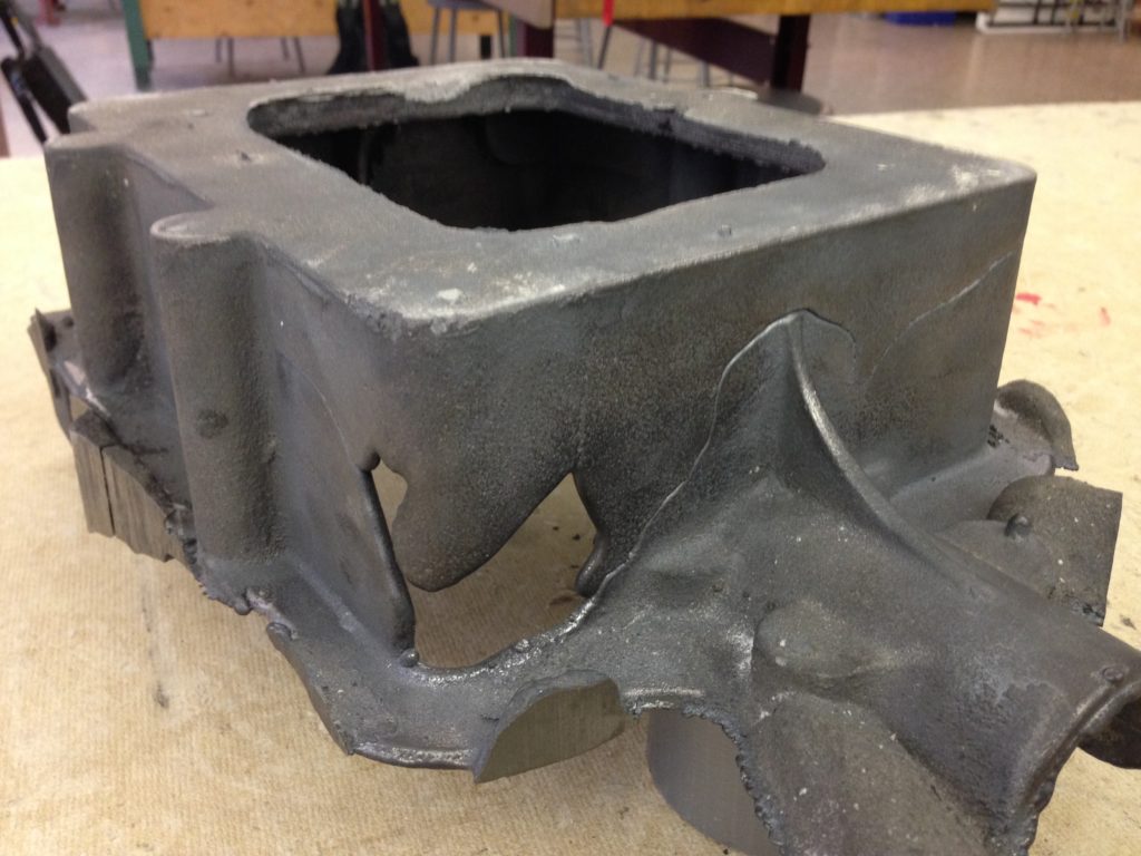
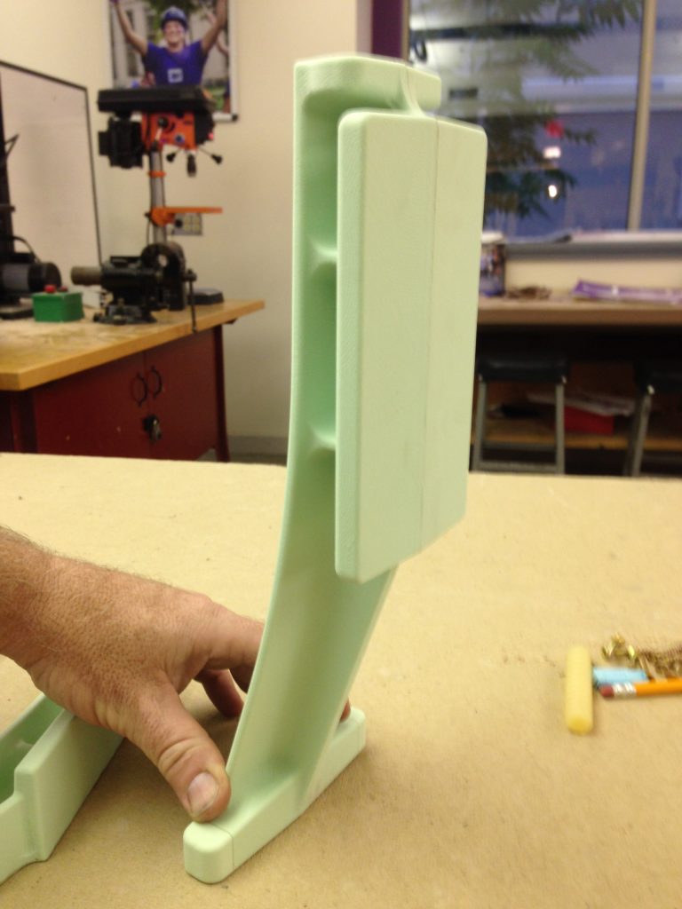
The base seemed simple. But like the cylinder caps, was of thin walled section and the coring was particularly complicated. The design called for undercuts for supporting gussets and shaft bearings, and had the added complication of a side pull to provide mounting bosses on the outer face of the base for bulkhead mounting. We debated eliminating this detail since the engine would not be mounted on any bulkheads, and doing so would simplify matters. But the student in charge of this part, Zach, along with the entire group wanted to remain as true to the original design as possible. Noble spirit.
The core consisted of at least six separate parts, with two of these parts requiring a four-part core-box. This was getting serious. We surmised the base was poured with the pattern upside down, filling from what would otherwise be the top flange and bearing mounts, up along the side walls, then finally filling the bottom of the base. This part, like the cylinder heads, and others, required a few attempts and a second semester. A pattern was developing. The weather, warming.
We celebrated our learning and took stock in key learning achievements. The Wizard of Bristol was not quick to reveal his secrets, but the group was undeterred. The Heart of the Engine was in hand, and we had a solid plan for next year’s group. The junior apprentices witnessed the seniors’ challenges and were keen to complete what had been started. We now had some experience and clarity about what lay ahead. Now it was time to send our seniors off to their next great adventure, enjoy our summer, and look forward to more Herreshoff engine work, Spring of next year. And to convince Kurt it would get done in time.
Second Senior Class: The Pressure is On
Spring 2018 would be our second semester on this project, and the last remaining opportunity to complete the engine with a larger group of students. Last year’s junior apprentices were now seniors, and we welcomed new faces to the group as well. No dawdling allowed.
Aluminum Bronze in the Early Days
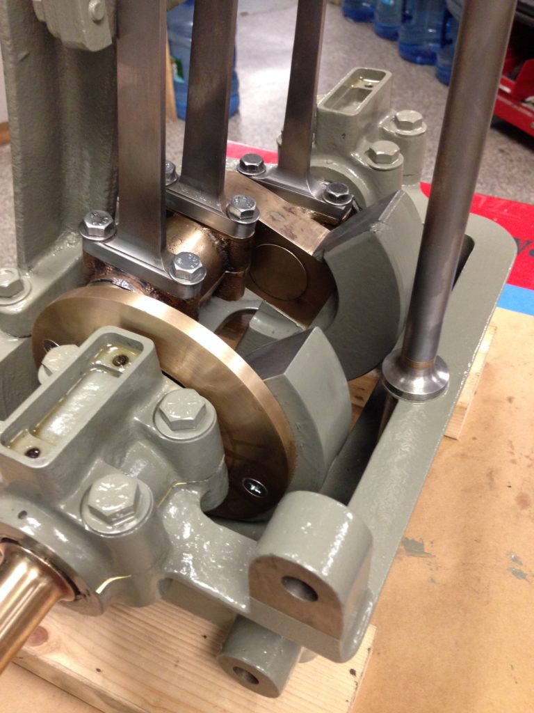
As a marine engine, there is no surprise in that gray cast iron and bronze was used throughout. Of the bronze, silicon bronze and close cousins would have been used. What was surprising, however, was the use of aluminum-bronze for the crankshaft. A fine material, no doubt! It has favorable wear characteristics, is 10% lighter than comparable bronzes, and has high yield and tensile strength. Nathanael Herreshoff certainly concerned himself with weight reduction and strength to weight ratios throughout his work. But the use of aluminum was a surprising and fascinating choice, since industrial processes for aluminum production were only becoming available in the 1890s, a few years before Captain Herreshoff penned the drawings. His small note “Alum-Bz Shaft” above the throw of the shaft must have been an expensive, bleeding-edge proposition for the U.S. Navy. “Plus ça change, plus c’est la même chose,” I suppose.
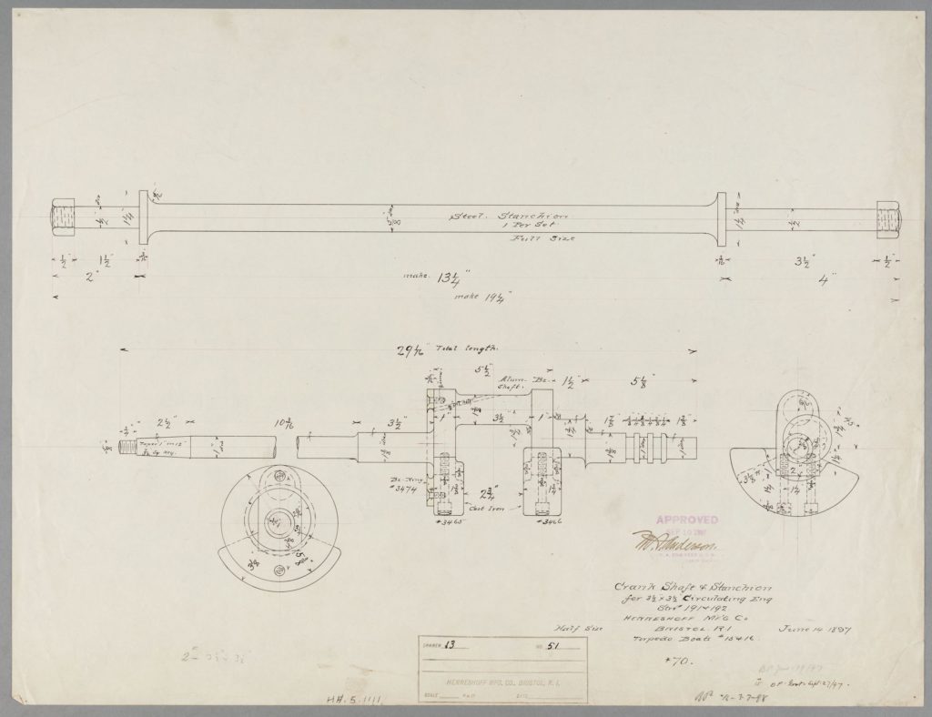
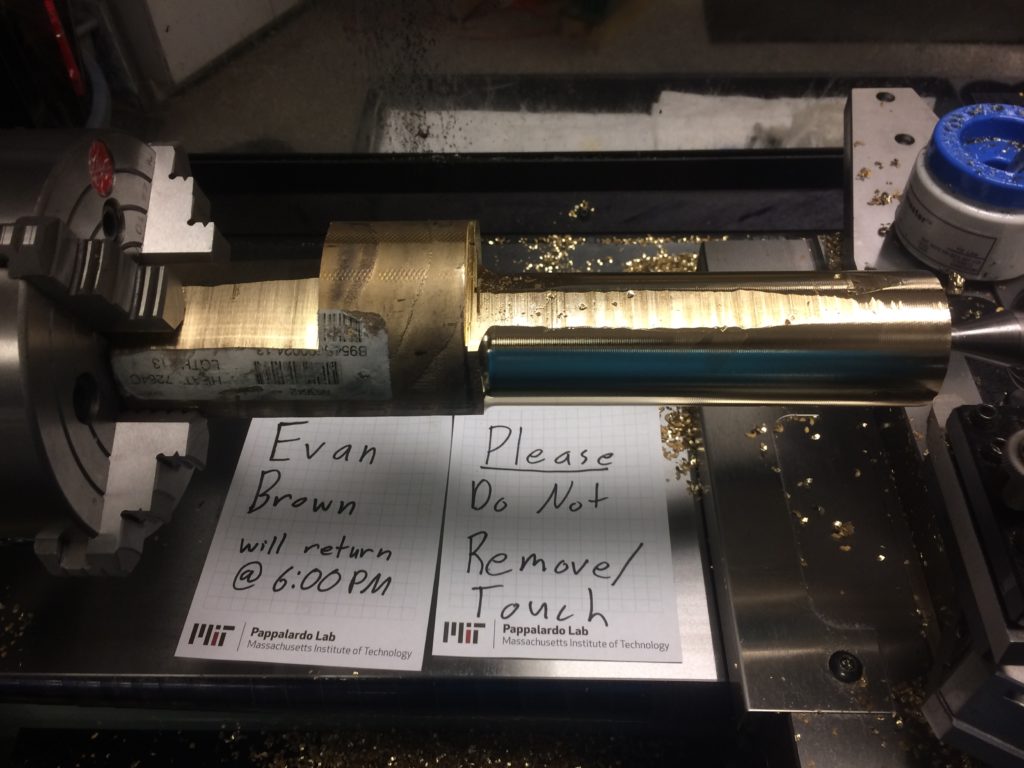
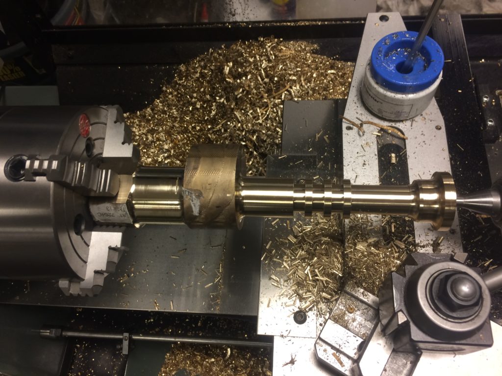
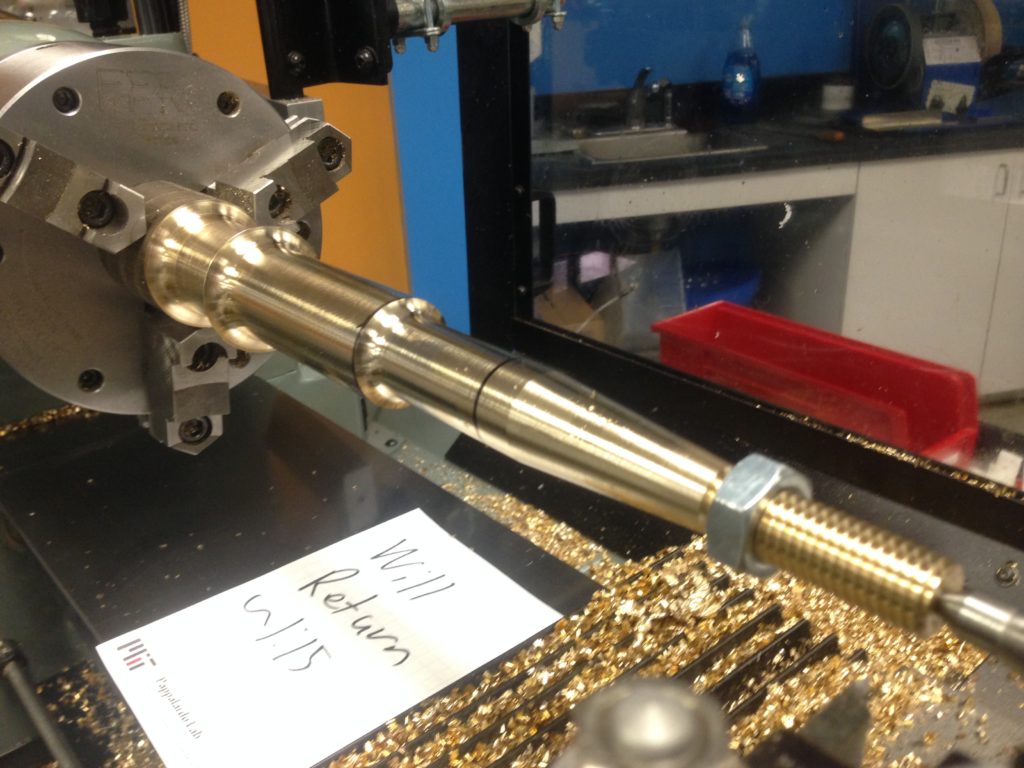
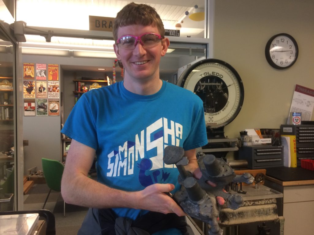
Evan was to tackle this part. We decided to machine the crankshaft of multiple pieces, and press and pin them together. In addition to the crankshaft, Evan cast the counterweights without incident. This was no ordinary turning job. Evan expertly turned each part and ground custom tools to achieve a specific flange radius to match bearing shells. The throws themselves required an offset to achieve correct valve timing. Evan got to know our Hardinge lathe intimately that term.
The Michelangelo of Connecting Rods
With the exception of the crankshaft, all the engine parts were either cast iron, cast silicon bronze, or machined from wrought stock - we knew what to do. Except for the connecting rods. The connecting rods are those elements that transmit the piston’s linear motion to the crankshaft’s rotary motion, and are subject to large compressive and tensile loads. Because of these large, cyclical impact loads, connecting rods are often forged to produce a high-strength microstructure. As a project onto itself, we could have worked with our friends at the foundry and forge, but felt that forged connecting rods were a bit beyond the scope of what our team could accomplish given our time constraints. I now had approximately eight weeks of “senior time” remaining. Cast steel was possible, but not entirely appropriate. CNC machining was a distinct possibility, though this approach seemed a bit of a dodge. Since the rods were largely flat, we planned cutting the outline on a bandsaw and then hand filing the faces. These were John Bell’s parts to own, and I thought some bench work would suit him well. Paraphrasing John:
“Why use a bandsaw on a large chunk of steel when we could more accurately cut the part on our waterjet?”
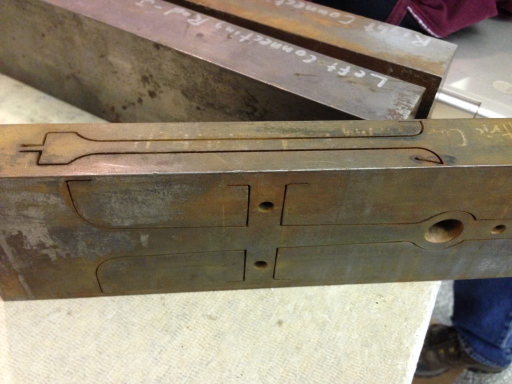
This was a difficult-to-argue point. The waterjet and its pumps and chiller occupy approximately 150 square feet in an area previously used for utilities servicing Building 3. Having commandeered this space many years ago, our waterjet now resides along electrical service panels, steam pipes, water supply lines, waste lines, and an assortment of other Institute infrastructure of unknown purpose. It’s a “watch-your-head” type of space.
“John, the waterjet would be perfect.”
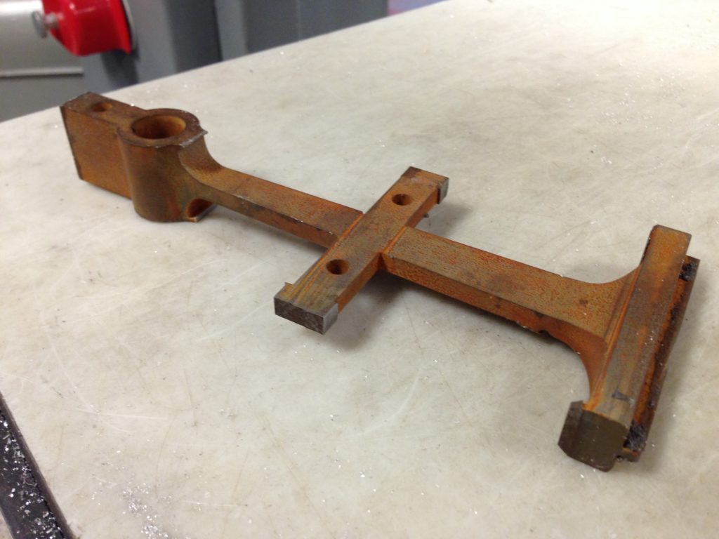
Furthermore, if instead of completely cutting the outline of the connecting rods with the waterjet, we instead left the part tabbed in place, the partially cut rectangular stock could be turned on its side and the front-to-back profile could subsequently be cut. By performing these two orthogonal two-dimensional cutting processes, a resulting three-dimensional connecting rod would emerge from the square material.
John commented, “I saw the connecting rod in the steel and carved until I set it free.”
“Funny John. Get it done.”
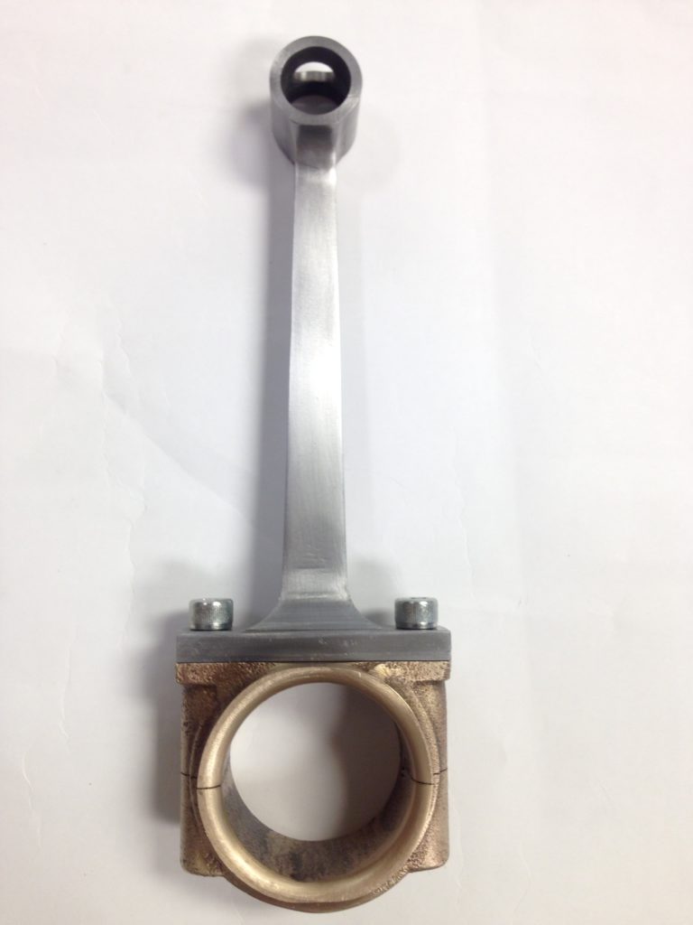
Since the engine wasn’t being put into service, we were comfortable bypassing the strength ordinarily achieved by forging, avoided the pedestrian “just use the HAAS machining center,” and had a fun educational time setting connecting rods free. After days of bench-work, John’s rods were mated to Annie’s bearings. It was coming together.
Sidebar about John: He is now a graduate student at MIT and recently passed his Ph.D. qualifying exams. John stopped by the lab earlier in March to cut some wood for a game table. He asked, “Umm, Dr. Braunstein, have you heard of a game called Dungeons & Dragons?” Ohhhh….out of the mouths of babes.
The Bed, Again
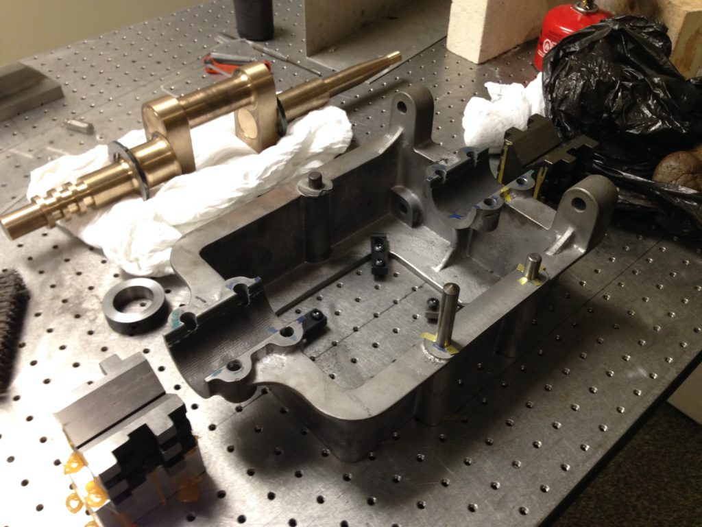
Zach’s patterns from the previous year were reworked to facilitate removal from the sand and the core – sand empathy, remember? The first pour attempt resulted in a cold weld along the bed bottom: the iron filling the right side cooled enough to freeze just as it was meeting the front of cooling iron of the left side. The result was what looked like a large fault line through the base. To remedy this, the gating arrangement was altered to allow for faster filling. But one additional attempt later, the bed was complete. Our learning was paying off. The bed was another symbolic component along with the cylinder. Onto it, Evan’s crankshaft, Emily’s shaft bearings, and Bibit’s vertical bearing column could be mounted. The engine was finally developing from an array of disparate components into a cohesive assembly.
The Connective Tissue
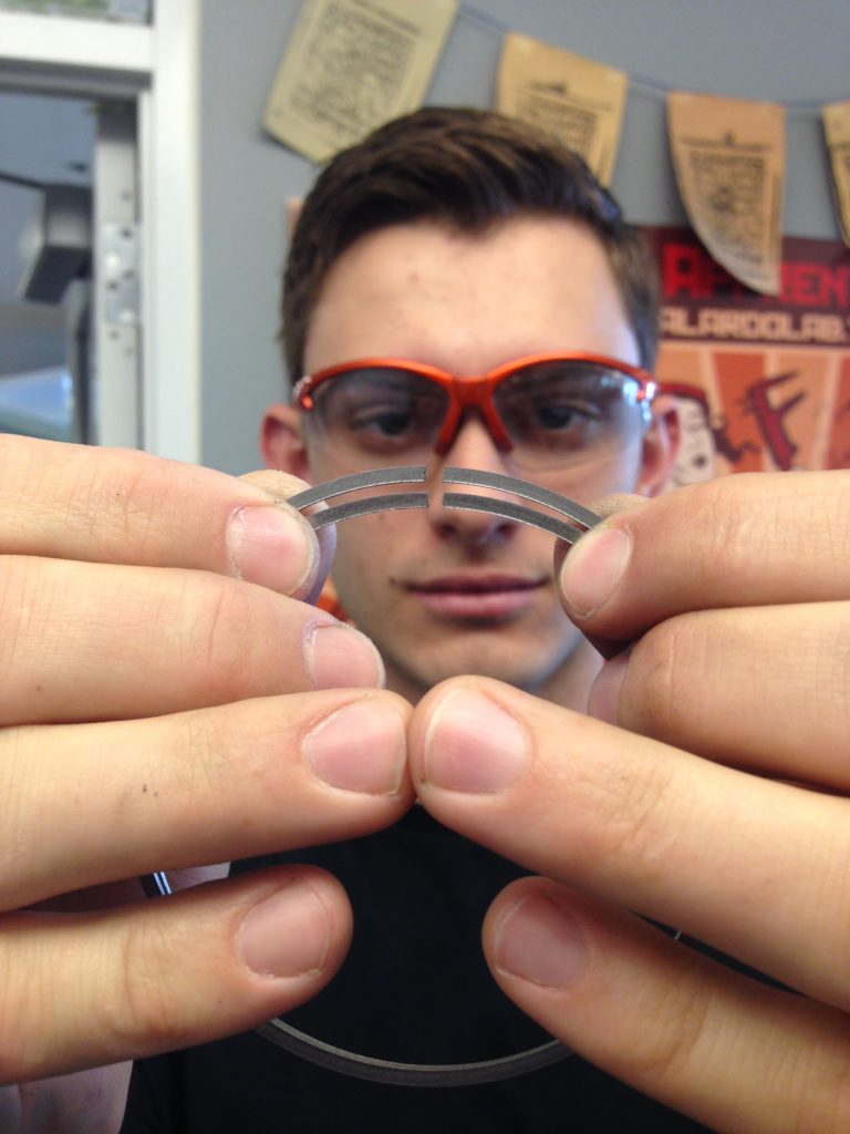
Many remaining parts were moving towards completion by spring break, and it was apparent that the whole team, including instructors, were working at a pace and developing expertise whereby we knew this engine was going to get done for the museum’s exhibition. Kurt dropped by occasionally to say hello. It was an exciting time. By late April 2018, everyone was firing on all cylinders. Any reticence from earlier that term had evaporated. The piston, valve, and fussy details of the valve rings were brilliantly being worked out by Sam. Sam’s parts were of such a fine quality. His castings were flawless as was his machining and polishing. Bibit attempted to cast the cross-slide bearing of aluminum bronze for sport, but the material’s troublesome solidification shrinkage created voids in the center of the part. Switch to another alloy – problem solved. A practical decision, under the circumstances. Rather than staring quizzically at our three-axis mill or wondering where to apply draft angles or fillets, the group was now generating g-code independently, grinding and filing their parts, and operating the mills and lathes with purpose and confidence. Students would point out porosity defects, discuss pour temperatures, and debate whether Herreshoff was the Wizard of Bristol or Oz. There was a superlative vibe in the lab that was infectious.
Wrapping Up
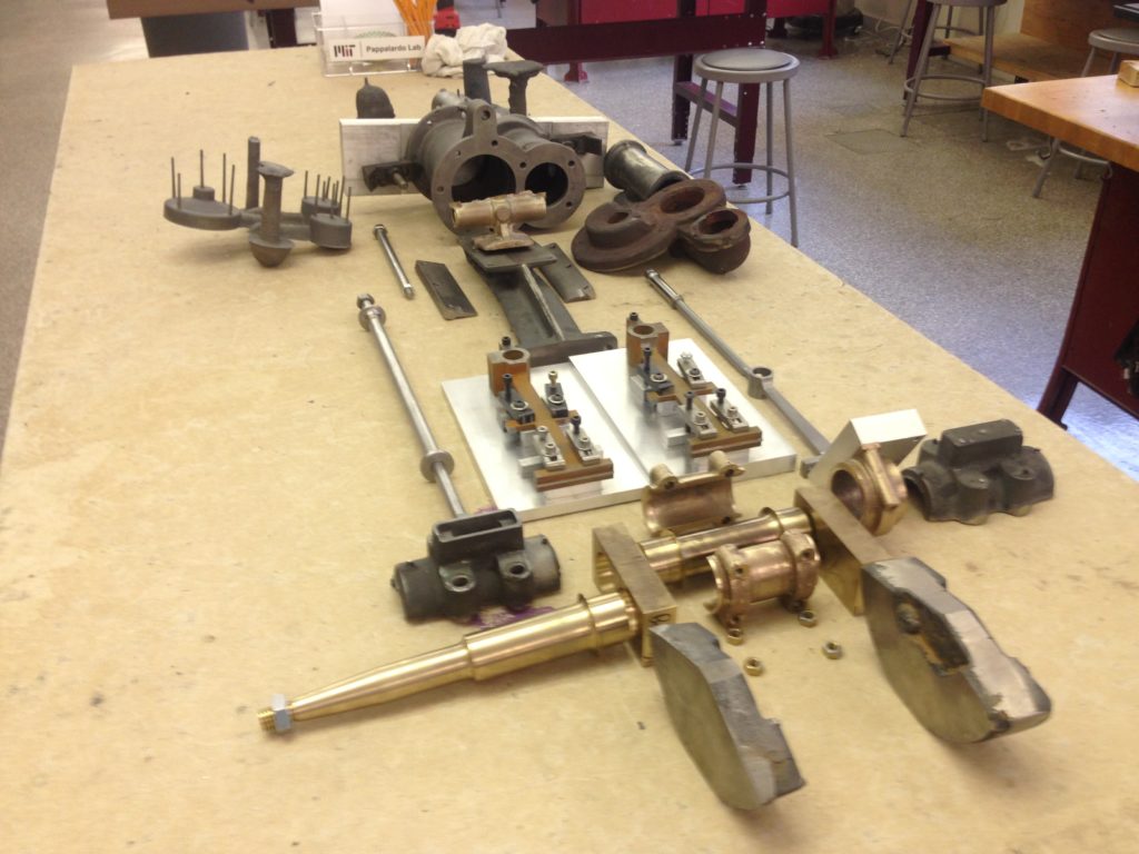
Senior spring is a time when our battle-hardened students realize they are wrapping up their tenure at MIT. Plans for next year have generally taken shape and for many, it is the first time in a very long time they choose to relax. Their work at MIT isn’t done, but the stakes are now different – very different. Fortunately, by the time June commencement rolled around, most engine parts were either complete or very near completion. Our first successful part, Colleen’s cylinder, had been patiently waiting for over a year for Shirley’s completed caps. Sam’s valves, piston, rings, and rods glistened, Zoe’s packing glands were receiving their final finish, and Johnny Bell’s connecting rods were polished and waxed. Evan was winding down the crankshaft and counterweights, Bibit’s bearing and column waited, and Emily’s bearing caps were fit to the base. Annie’s bearings were fit the to the piston connecting rod, while “Yasmin? Yasmin? Your bearings?” Yasmin had been with the lab since her sophomore year and had a standing heart rate of, at most, half mine. Yasmin’s bearing caps, too, were complete. But not without the quip, “Senior spring is hard.”
Delivery
By mid-May, our seniors were done. Their time as MIT undergraduates had reached its conclusion and the 2018 apprentice team was dissolved. Virtually everything had been completed, and any remaining items could be finished over the summer and fall by our staff and perhaps an interested student. The exhibition was now opening in October, which provided ample time to wrap up. During our quieter summer, Bill put finishing touches on Evan’s multi-part aluminum bronze crankshaft and Scott cleaned up some of the castings – a weld here and there, grinding, etc. When I returned to campus in the fall, I turned to pouring the Babbitt bearings for the crankshaft, getting the engine running, and painting. Final assembly was straightforward, thanks to the quality of the students’ parts. No shimming was necessary. Once the crankshaft bearings were lapped and all moving parts were oiled, we gave the little engine some compressed air. “Ka-chug….ka-chug”. It stalled. After a few more attempts and a tweak here and there to reduce friction in the assembly, we increased air pressure a skoch, and “Ka-chug….Ka-CHUG….KA-CHUG!!!” This time, it took off and kept going.
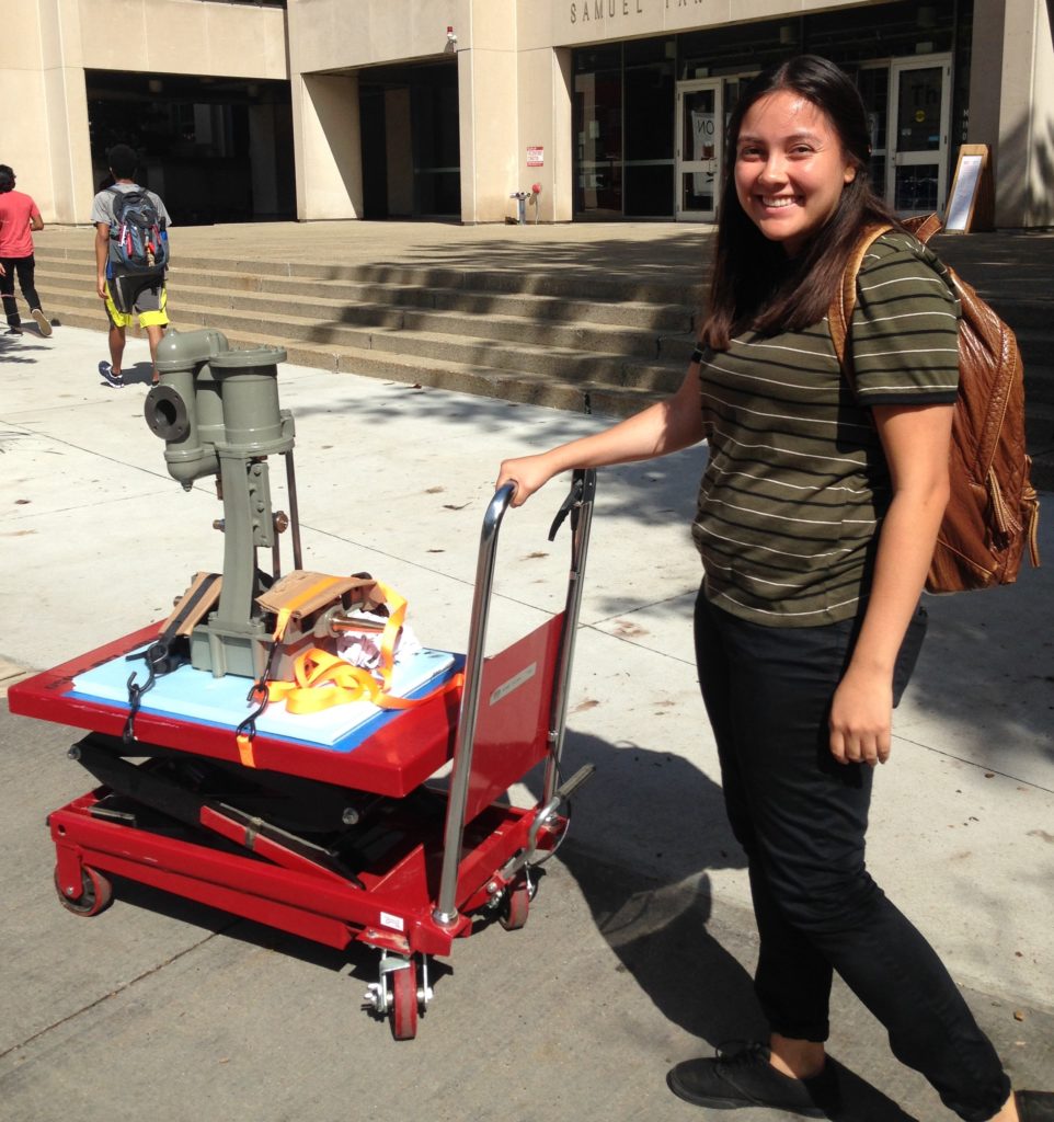
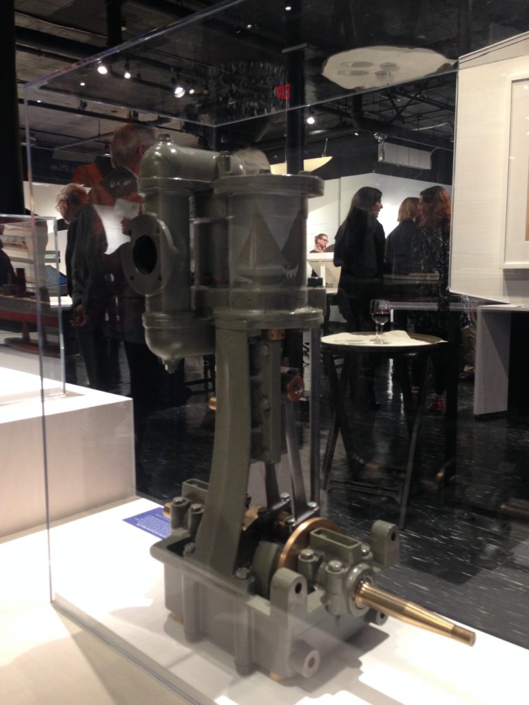
It was time. Our little engine was complete, painted, and ready to be sent to the museum. Forms had been signed in advance, and there was an email exchange about custody, transport, and some comment about insurance. “Huh?” I thought. Yasmin, now a graduate student, strapped the engine to a lab cart and she and I wheeled it up Massachusetts Avenue – the same route I walked two years prior to chat with Kurt. Within a week from delivery, our newly fabricated and functional HMCo. steam engine, representing two years of student work, glistened within its vitrine during the exhibition’s opening night. A full house of Herreshoff aficionados and museum supporters celebrated an amazing exhibit.
Post-Script
This project was completed over the course of two spring semesters, part-time fall work, and some activity over the summer of 2018. It involved approximately fifteen students, and five instructors/coaches/mentors. Our entire lab staff was involved - Steve Haberek, Scott Spence, Jim
Dudley, Tasker Smith, and Bill Cormier. Bill, in particular, was instrumental in working directly with students in the machine shop. Bill developed custom one-off fixtures and identified the necessary tools we would need to complete this project. He stood side-by-side with the apprentices showing them tricks-of-the-trade and best practices, and made sure they were successful, diligent, and uncompromising. This project, and any of the apprentice projects, was only possible with the generosity of our friends and colleagues down the hall in the Department of Material Science and Engineering – Mike Tarkanian, James Hunter, Tara Fadenrecht, and Shaymus Hudson.
Our students have since graduated, a few remaining at MIT for graduate school, some at campuses elsewhere – Stanford, Penn, Cambridge, and others starting careers with a variety of private and public enterprises – from companies such as Milwaukee Tool and Apple, to smaller tech start-ups, consultancies, and global NGOs. A new generation of apprentices are currently working to fabricate the anchor windlass used on Herreshoff’s 529 class of cutters, and the Lunenburg engine project continues.
Dr. Braunstein is a Senior Lecturer at the Massachusetts Institute of Technology in the Department of Mechanical Engineering and Director of the Pappalardo Undergraduate Teaching Laboratories. When not teaching in the fields of product development and mechanical design, Danny will often be found sailing his centenarian Lawley sloop. He can be reached at [email protected] and would be glad to field questions about this project!